|
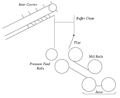
You are here : Control System Design - Index | Simulations | Sugar Mill Problem Sugar Mill Case StudyWhile the focus of the previous examples has been experimenting with a simple problem in a JAVA applet, the focus of this section is somewhat broader, throwing an open-ended, non-trivial problem out to whoever is willing to take it on. The system in question is a sugar mill, chosen because it includes significant multivariable interaction, a non self regulating nature and non-minimum phase behaviour. (photo) The sugar mill unit under consideration constitutes one of multiple stages in the overall process and can be represented, in a very simplified way, as shown below.
In this mill, bagasse (in intermediate form), which is milled sugar cane, is delivered via the inter-carrier from the previous mill stage. This is then fed into the buffer chute. The material is fed into the pressure feed chute via a flap mechanism and pressure feed rolls. The flap mechanism can be manipulated via a hydraulic actuator to modify the exit geometry and volume of the buffer chute. The pressure feed rolls grip the bagasse and force it into the pressure feed chute. Cane is then fed to the pressure feed chute through the mill rolls. The pressure feed chute increases the compression ratio of the bagasse, because the pressure feed roll surface is slightly higher than the mill roll speed. The mill rolls are grooved, so that no expressed juice can escape. The grooves are given a rough surface so that the mill rolls can grip the cane. The mill rolls and pressure feed rolls are driven by a steam turbine through a gear system. The steam turbine speed is controlled with a governor feedback system with an adjustable set point. For the purpose of maximal juice extraction, the process requires the
control of two quantities: the buffer chute height, h(t),
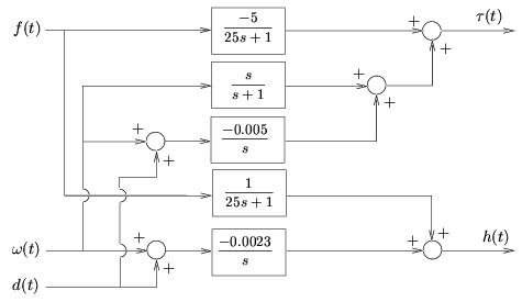
and the mill torque In this example, regulation of the height in the buffer chute is less important for the process than regulation of the torque. Indeed, the purpose of this chute is typically to filter out sudden changes in the feed. After applying phenomenological considerations and performing different experiments with incremental step inputs, a linearized plant model was obtained. The outcome of the modeling stage is shown below.
From the above figure we can compute the nominal plant model in RMFD
form, linking the inputs f(t) and
where
The control of this system is difficult because it has a non-minimum phase zero (which is not evident from the transfer function - where does this come from?), it is highly interactive and is marginally stable (which is evident in the transfer function). You can download a model of this system (in Matlab format) by clicking here. Once you have done this, the challenge is open to you - design a controller for this system, remembering that regulation of the torque is most important. The list below shows some controllers you might like to try to design.
This problem is left as a challenge for you, the reader, in the hope that you might learn much from attempting this design. If you are interested in a possible solution, you might like to read chapter 24 of the book. The purpose of this exercise is not the end result (a beautiful, robust controller), but the process of learning while designing a controller for a real industrial system.
|

