You are here : Control System Design - Index | Simulations | Inverted Pendulum | Part 5
Inverted Pendulum Tutorial - Part 5
Before continuing, make sure you have read Chapter 17, Chapter 6 and Chapter 7.
State Feedback Control
Now we will attempt to design a state feedback controller for the inverted pendulum system. We will design this controller under the assumption that both the pendulum angle and cart position can be measured. (Note, if we assumed that only the cart position could be measured, we would be facing a difficult problem as before - i.e. using a state feedback controller with an observer would provide us with no advantages over the previous design.)
The state space form of the system is:

Since we assume that angle and position can be measured perfectly, the C matrix for the system is

First, we note that the system is controllable, since the controllability matrix

is invertible. The system is also observable, so there is point in continuing in the design of the state feedback controller.
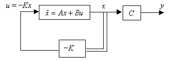
We first design the controller, ignoring the observer. In state feedback control, we set f = - K x, where K is the control matrix. The following diagram illustrates this:

The poles of the closed-loop system are the roots of the polynomial
det(s I - (A - B K))
The next step is to choose the desired location of these closed loop poles. Arbitrarily, let the closed loop system have two poles at -1 and poles at -1 ± j. The K matrix is then found from equating the coefficients of powers of s in the desired closed-loop polynomial and the actual closed loop polynomial:
s4 + (2k2 - 2k4)s3 + (2k1 - 2k3 -20)s2 - 20k2s - 20k1 = s4 + 4s3 + 7s2 - 6s - 2
Solving this equation yields
K = [ k1 k2 k3 k4 ] = [ -0.1 -0.3 -13.6 -2.3 ]
which is the required controller. However, not all of the state variables are measurable, so we must use an observer to reconstruct the state variables of the system from the outputs which can be measured. Due to the choice of state variables, this is an especially easy task in this case, since the variables which cannot be measured are simply the derivatives of the cart position and pendulum angle. Remembering that we cannot implement a pure derivative, the observer is

The diagram below shows the closed loop system including the observer.

The JAVA applet below shows the simulation of the closed loop state feedback controller/observer system. The interface is very similar to previous ones: use the "Change Parameters" button to alter the system parameters. This time, instead of altering the transfer function of the controller, you change the K vector of the controller. The left-most text entry field represents k1 and the rightmost one k4. The observer is fixed, and cannot be changed by the user.
The system state variables can also be altered instantaneously. This
can be used to simulate step responses, since the controller will try to
drive the system's state to zero. The state fields, in order from left to
right, are ![]()
| Things to try | Things to notice |
| Run the simulation | The overshoot in this worse than the cascaded system (not by much), but still much better than original controller. |
| Change the controller to K = [ -4.5 -5.7 -42 -11.7 ], which gives two closed loop poles at -3 and poles at -3 ± j. | The cascaded system is better at attenuating measurement noise (even though both the angle and position measurements are noisy) |
| Try to design a controller which gives the closed loop system two poles at -5 and poles at -5 ± 3j. | N/A |
Notice that the controller is as good as the previous cascade controller, since the same two variables are being measured. This controller also has similar noise rejection capabilities to the cascade controller.