Rolling Mill Shape Control - Part 1
Before continuing, make sure you have read Chapter 21 and Chapter 24.
System Model
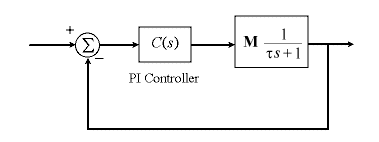
The model for the system is shown in the block diagram below, where U vector of spray valve positions and Y is the roll thickness vector. (The bold lines indicate vectors rather than single signals).

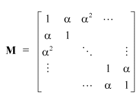
The sprays affect the roll as described by the matrix M below.

The parameter ![]() represents the level of interactivity in the system, and is determined by
the number of sprays present, and how close together they are.
represents the level of interactivity in the system, and is determined by
the number of sprays present, and how close together they are.
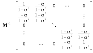
This matrix has a simple inverse as shown below.

Using this matrix to decouple the system amounts to turning off surrounding sprays when a spray is turned on.
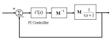
So we can decouple the system simply by multiplying the control vector by this inverse. This set up is shown in the block diagram below.

The controller is then a set of simple PI controllers linking each shape meter with the corresponding spray. (We assume that the shape meters measure the shape of the rolls perfectly).
It may at this stage seem that adding more sprays will give finer
control of the roll shape. However, as more sprays are added, ![]() approaches 1. The system is then less robust, since the matrix M is
almost all 1s, and the inverse of M has very large numbers. The
system is then very sensitive to errors in the estimation of alpha, due to
the large gains present in M-1.
approaches 1. The system is then less robust, since the matrix M is
almost all 1s, and the inverse of M has very large numbers. The
system is then very sensitive to errors in the estimation of alpha, due to
the large gains present in M-1.
Java Applet Simulation
The JAVA applet below is a simulation of the shape control system. There are 10 sprays, and the graph has a vertical scale of 1mm per division and a horizontal scale of 2 seconds per division. It shows the position set-point (the blue trace) and five of the rolling mill thicknesses (the other colours).
Pressing the "Change Parameters" button allows you to change
the set-point type. "Uniform" means that the set-point is
uniform across the roll, "Square" means that the set-point is a
step across the roll, and "Point" means that a single point on
the roll has the changing set-point. The parameter window also allows you
to change the PI controller parameters and the amount of measurement noise
in the shape meters. The decoupling compensation (the inverse of M)
can be enabled or disabled through the check box. Also, the parameter ![]() can be altered to change the level of interactivity between the sprays. If
you check the "Reset roll to default state" box, the roll shape
will be reset to its (bumpy) initial shape. Try experimenting with these
parameters.
can be altered to change the level of interactivity between the sprays. If
you check the "Reset roll to default state" box, the roll shape
will be reset to its (bumpy) initial shape. Try experimenting with these
parameters.
| Things to try | Things to notice |
| Disable the decoupling and change the set point to "Point" | Notice the interactivity between the sprays |
| Enable the decoupling (resetting the roll shape) | Notice the improved (i.e. both faster and completely decoupled) response. |
| Disable the decoupling and change the set point to "Square" and then "Uniform" | Notice the interactivity between the sprays |
| Enable the decoupling (resetting the roll shape) | Notice the improved (i.e. both faster and completely decoupled) response, particularly in the square set point. |
| Change the value of alpha (the interactivity parameter) with decoupling disabled (Ensure that alpha < 1 or instability results) | Notice that lower alpha values improve the response, and alpha = 0 is equivalent to enabling decoupling. |
Note that in this simulation, we were applying step set-point changes. In practise, the set point is fixed, but output disturbances occur. Applying step set-point changes is similar to applying step output disturbances, as a very similar type of response would be seen.
The decoupling method works extremely well. The highly interactive system becomes completely decoupled, allowing control using simple PI controllers. Next, we examine the effect of saturation levels on the valves.