|
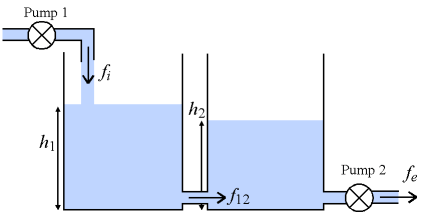
You are here : Control System Design - Index | Simulations | Tank Level Tank Level TutorialBefore continuing, make sure you have read Chapter 7 and Chapter 19. System DescriptionAt the University of Newcastle, the Centre for Integrated Dynamics And Control (CIDAC) runs a short course on control systems. Part of the lab work for this course consists of designing a controller for a pair of coupled tanks, as shown in the diagram below.
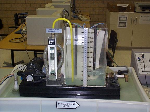
Water flows into the first tank through pump 1 a rate of fi which obviously affects the height of the water in tank 1 (denoted by h1). Water flows out of tank 1 into tank 2 at a rate of f12 , affecting both h1 and h2 . Water then flows out of tank 2 at a rate of fe controlled by pump 2. Given this information, the challenge was then issued to the students of the course: control the heights of the tanks. However, a problem arose when the sensor for the height of tank 1 failed. Graham then suggested that it would be possible to build a virtual sensor (or observer/soft sensor) to estimate the height of tank 1 based on measurements of the height of tank 2 and the flows f1 and f2. Overview of the ExampleIt is recommended that you follow the example in order, but you may skip ahead if you wish:: Photo of the SystemThe actual tank apparatus at the University of Newcastle is shown in the photo below.
AcknowledgementsThe original work on this system was done by Adrian Wills at the Department of Electrical & Computer Engineering, University of Newcastle Australia.
|

