|
You are here : Control System Design - Index | Book Contents | Chapter 2 | Section 2.3 2. Introduction to the Principles of Feedback
|
 : : |
commanded level of steel in mould |
 : : |
actual level of steel in mould |
 : : |
valve position |
 : : |
casting speed |
 : : |
inflow of matter into the mould |
 : : |
outflow of matter from the mould. |
Physics suggests that the mould level will be proportional to the integral of the difference between in- and outflow:
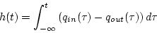 |
(2.3.1) |
where we have assumed a unit cross-section of the mould for
simplicity. We also assume, again for simplicity, that the
measurements of valve position, v(t) and casting speed,
 ,
are calibrated such that they actually indicate the
corresponding in- and outflows:
,
are calibrated such that they actually indicate the
corresponding in- and outflows:
 |
(2.3.2) |
 |
(2.3.3) |
Hence, the process model becomes
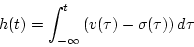 |
(2.3.4) |
The casting speed can be measured fairly accurately, but mould-level sensors are typically prone to high-frequency measurement noise, which we take into account by introducing an additive spurious signal n(t):
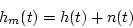 |
(2.3.5) |
where hm(t) is the measurement of h(t) corrupted by noise. A block diagram of the overall process model and the measurements is shown in Figure 2.3.
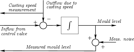
This is a very simple model, but it captures the essence of the problem.