|
You are here :
Control System Design - Index | Book Contents |
Chapter 2
| Section 2.7
2. Introduction to the Principles of Feedback
2.7 From Open- to Closed-Loop Architectures
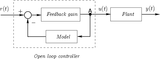
A particular scheme has
been suggested in Figure 2.7 for realizing an
approximate inverse of a plant model. Although the controller in
this scheme is implemented as a feedback system, the control is
actually applied to the plant in open loop. In particular,
we see that the control signal u(t) is independent of what
is actually happening in
the plant. This is a serious drawback, because the
methodology will not lead to a satisfactory solution to the
control problem unless
- the model on which the design of the controller has been based
is a very good representation of the plant,
- the model and its inverse are stable, and
- disturbances and initial conditions are negligible.
We are thus motivated to find an alternative solution to the
problem, one that retains the key features but does not suffer
from the above drawback. This is indeed possible by changing the
scheme slightly so that feedback is placed around the plant
itself rather than around the model.
To develop this idea, we begin with the basic feedback structure
as illustrated in Figure 2.9. We proceed as follows.
Figure 2.9:
Open-loop control with built-in inverse
 |
If we assume, for the moment, that the model
in Figure 2.9
is perfect, then we can rearrange the diagram to yield the
alternative scheme shown in Figure 2.10
Figure 2.10:
Closed-loop control
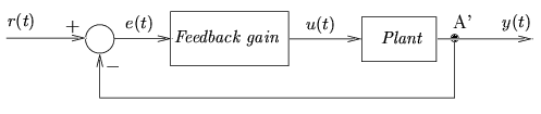 |
This scheme, which has been derived from an open-loop
architecture, is the basis of feedback
control. The key feature of this scheme is
that the controller output depends not only on the a-priori data
provided by the model but also on what is actually happening at
the plant output at every instant. It has other interesting
features, which are discussed in detail below. However, at this
point, it will be worthwhile to carry out an initial discussion of
the similarities and differences between open- and closed-loop
architectures of the types shown in
Figure 2.9 and
Figure 2.10.
- The first thing to note is that, provided that the model represents
the plant exactly, and that all signals are bounded (i.e., the loop
is stable), then the schemes are equivalent regarding the
relation between r(t) and y(t).
The key
differences are due to disturbances and different initial conditions.
- In the open-loop control scheme the controller incorporates
feedback internally: a signal at point A is fed back. In
closed-loop control, the signal at A' is fed back. The fundamental
difference is that, in the first case, everything happens inside the controller,
either in a computer or in some
external hardware connection. In the second case, the signal
fed back is a process variable: measuring devices are
used to determine what is actually
happening. The heuristic advantages of the latter alternative are
undoubtedly clear to the reader. We will develop the formal
background to these advantages as we proceed.
|