You are here : Control System Design - Index | Simulations | Inverted Pendulum | Part 2
Inverted Pendulum Tutorial - Part 2
Before continuing, make sure you have read Chapter 5.
Control Design
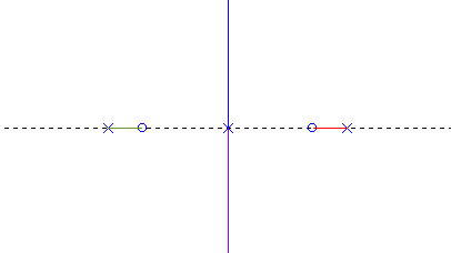
The control of the inverted pendulum system is very hard. As a starting point, consider proportional control and look at the resulting root locus. For positive gains K, the root locus is:

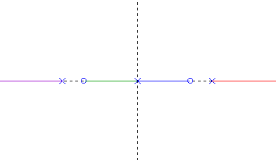
and for negative gains:

Notice that in both these plots, there is a branch of the root-locus that is always in the right half plane. Hence, no matter what the gain, the system will always be unstable, so we instantly conclude that proportional control is no good. We must do something to attract this branch of the root locus back to the left half of the complex plane. PID control will certainly not do this for us, since an integral term adds another pole at the origin.
The pole assignment control design method uses the Diophantine equation. This equation is:
L A + P B = Acl
where A has degree n and B has degree at most n. This equation can always be solved to give the controller P / L for the plant B / A provided that P and L have degree n - 1 and Acl has degree 2n - 1.
For the inverted pendulum, we have
| A = s4 - 20s2 |
| B = 2s2 - 20 |
so we must choose P and L to have degree 3 and Acl to have degree 7. Now, set the desired closed-loop poles in Acl at
| -10+3j | -10-3j | -10+3j | -10-3j | -0.5 | -0.5 | -0.5 |
Solving for P and L using the Sylvester matrix, we get the following coefficients for P and L:
| s3 | s2 | s1 | s0 | |
| P | 1690.5 | 7213.0 | -472.79 | -74.256 |
| L | 1 | 41.5 | -2682.3 | -8278.9 |
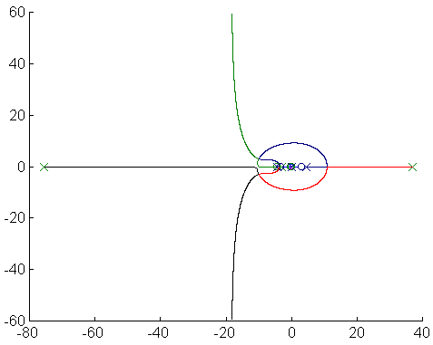
The root locus for the entire system is shown below.

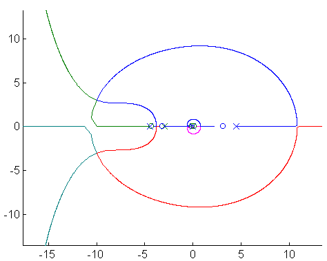
Magnifying:

Note that the controller has introduced zeros at -4.3290, 0.1366 and -0.0743 and poles at -75.5518, 37.0124 and -2.9606 : i.e. both the controller and the plant have an unstable pole and a non-minimum phase zero. We would thus conclude that the controller is not "sensible", since it is not very robust. To illustrate this, try altering the controller in the following JAVA applet. This controller is very sensitive to noise due to its high gain (just look at the response in the presence of noise). If the system goes unstable and the angle approaches infinity, the pendulum will not be drawn (due to an interesting "feature" in JAVA's Math.sin), but the cart will still move around. To change the simulation parameters, press the "Change Parameters" button and you will be presented with a new window which asks you for various parameters, such as set point, noise level and the transfer function of the controller. The top row of numbers in this transfer function are the coefficients in P (starting with the coefficient of s3) and the bottom row of numbers are the coefficients in L. You can change the position set point by simply typing in a different number (although I recommend steps of only 0.1m).
You should try altering the noise level to see the effect of measurement noise. (As a technical note, the noise level is 10 times the peak amplitude of the noise). The scale of the graph is such that each vertical division represents 0.4m. If the simulation should become unstable, press the "Reset" button. Pressing the "Start" button will start the simulation, and pressing "Stop" with stop it. You can try to come up with a better controller using to pole assignment method. The blue plot is the cart position and the green plot is the pendulum angle.
| Things to try | Things to notice |
| Change the noise level to 1, 0.1 and 0 | The pendulum jerks around much more with the higher noise level. |
| Change the controller to achieve a better response with less overshoot | N/A |
As you may have noticed, the controller is not very good at controlling the cart position. Note particularly the 600% overshoot and undershoot in the response. Again, you might wonder whether this is due to poor control design or whether it is a fundamental constraint (you may wish to look at the inverted pendulum example in Chapter 13). You should be able to realise now that this is fundamental, and due to the nature of the system (i.e. a non-minimum phase zero and an unstable pole).
Next, we will examine what can be done if we measure angle as well as cart position.