|
You are here : Control System Design - Index | Simulations | Inverted Pendulum | Part 3 Inverted Pendulum Tutorial - Part 3Before continuing, make sure you have read Chapter 10 and Chapter 5. You might also want to refer to the frequency response applet here. Cascaded ControlIf we measure the angle of the pendulum as well as the cart position, controlling the inverted pendulum system is much easier. To see this intuitively, try balancing a broom on the palm of your hand with your eyes shut (i.e. you know cart position only) and with your eyes open (i.e. you know both position and angle). Generally, the angle is measured using a potentiometer (a type of variable resistor). A block diagram of the system is:
So we can form two control loops for the system, with the inner loop controlling the pendulum angle, and the outer loop controlling the cart position.
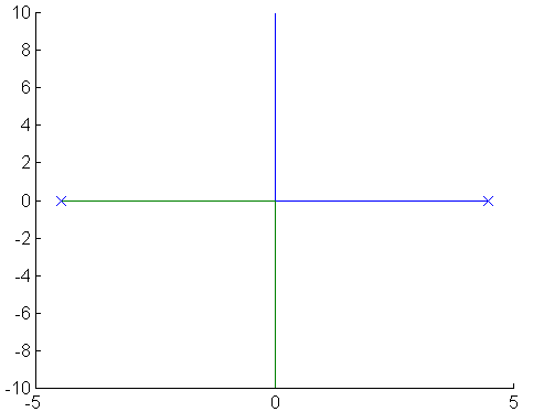
First, we design the controller for the inner loop. Let us use the root-locus design method. Since the inner plant has poles at +4.4621 and -4.4721, the root locus will look like:
If we use PD control, we have the controller C2 = kd s + kp, which allows us to place a zero on the real axis. If we place this zero on top of the stable pole, the root locus will have a single branch extending left from the unstable pole, so with a high enough gain, we can make the system stable. However, we never use a pure derivative in control (since it amplifies noise too much - look at its frequency response), instead we use a differentiator in series with a low pass filter. This low pass filter is chosen to have a bandwidth much larger than the system bandwidth. Thus, the implementation of the PD controller will be (with appropriate zero and gain choice):
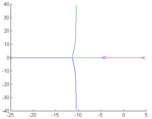
and the resulting root locus (with controller poles and zeros in purple) is:
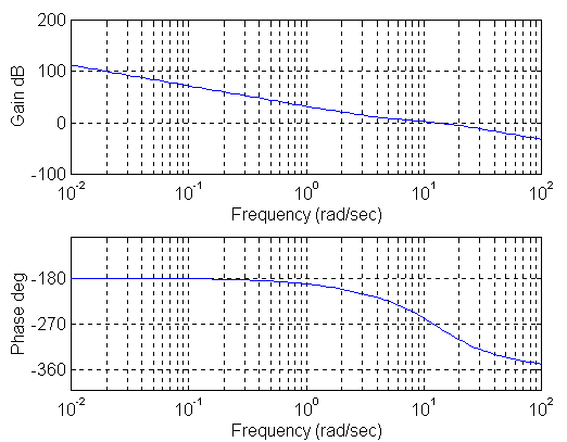
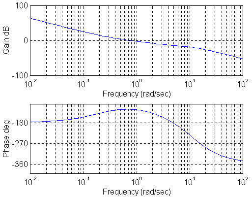
Note the effect of not cancelling the stable pole exactly. The effect of the added pole at -25 due to the low pass filter is to cause the root-locus branched to break away from the negative real axis. This could cause poorly damped oscillations if the gain of the controller is too high. For the design of the outer loop controller, we will use frequency response methods. A PD controller will be used, but such a controller is generally called a lead compensator when using this method. First, we look at the frequency response of the "plant" (which in this case is the closed inner loop system in series with the cart mechanics):
Note that this frequency response has a negative phase margin (which is given by 180° + p, where p is the phase shift at the frequency at which the gain is 1). For stability, a phase margin of more than 0° is needed, but for robust stability, a phase margin of 50° or more is suggested. The compensator is thus chosen as
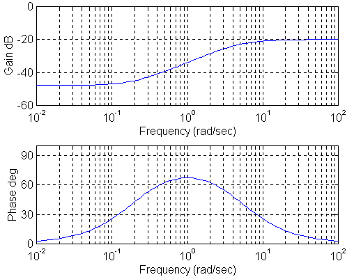
The frequency response of this compensator is shown below.
The lead compensator has three parameters which can be adjusted: the pole position, the zero position and the loop gain. Generally the pole and zero position differ by a factor of 10, which provides the desirable positive "bump" in the phase response. The positions of the pole and zero are chosen such that the compensator lead (or "bump") in the frequency response is at the optimal position relative to the plant's response (i.e. we are trying to boost the plant's phase response above 180°). The gain of the compensator is chosen to make the magnitude of the open loop system 0 dB at the peak of the phase response (to guarantee the phase margin). The frequency response of the entire open loop system is:
Note that the gain margin is now about 55°, which is acceptable. The gain margin (in case you're interested) is 8 dB (which is also acceptable for robust stability). The next page shows a simulation of this cascaded system. |


